Key takeaways:
The excerpt discusses key principles for designing machine electrical equipment in accordance with EN 60204-1, indicating typical hazards and the practical consequences of errors. It emphasizes prevention in situations involving hidden failures, as well as the importance of correct marking, protection against electric shock, and the emergency stop (E-STOP).
- EN 60204-1 describes the requirements for the electrical equipment of machinery to improve safety and reliability in industry.
- The difference between a defect condition (latent defect) and a failure was emphasized, as well as the need for protection already at the defect stage.
- Unambiguous identification of cables and components in accordance with IEC 60445 is required (PE yellow-green, N blue).
- Protection against electric shock includes, among other things, proper insulation and selecting an RCD appropriate to the nature of the installation (e.g., type B with variable frequency drives).
- Emergency stop devices must be clearly visible and readily accessible; EN 60204-1 refers to ISO 13850 (e.g., red on a yellow background).
Do you know how many hazards can arise in a machine with an apparently simple electrical installation? Incorrectly selected shock protection or improperly identified conductors can lead not only to downtime, but also to serious risks to operators’ health and lives. That is exactly why the harmonised standard EN 60204-1 sets out requirements for the electrical equipment of machines so precisely. The aim is to ensure safe, reliable, and efficient machine operation in an industrial environment. Below you will find an expanded discussion of the ten most important principles of designing machines “from the electrical side”, with practical examples and commentary on how this translates into day-to-day operation.
The difference between a fault condition and a failure – why protection is needed in a fault condition
In industry, a fault condition is often mistakenly equated with a failure, even though these terms differ in nature and have important safety implications:
- Fault condition – the machine already has a hidden defect, for example a cable with damaged insulation. However, this may not produce any obvious symptoms during normal operation. The machine continues to run, and the operator may not notice anything unusual. This is particularly dangerous because there is a potential source of electric shock, fire, or other hazards, while clear warning signs are absent.
- Failure – the device stops working, shuts down, or displays a clear error message. From the employee’s perspective, this often happens “suddenly”, even though the cause was an earlier, unnoticed defect (the fault condition mentioned above).
Why must a machine be protected already at the fault stage? Because when a defect does not show up in everyday use, the likelihood increases that it will develop into a more serious failure—and, worse, it can lead to an accident. A cable with damaged insulation is a classic example: no one notices a small crack because the machine operates normally. Only direct contact with the conductor can have tragic consequences, from electric shock to a worker to a short circuit and fire in the control cabinet. That is why it is so important to account for possible hidden fault conditions in the protection system and to carry out regular inspections to detect defects before they turn into failures with irreversible consequences.
1. Identification of conductors and components
One of the fundamental elements of designing electrical installations in machines is correct identification of conductors and components. The standard refers to IEC 60445, which defines colour coding and identification symbols.
- Protective conductor (PE): green-yellow.
- Neutral conductor (N): blue.
- Phase conductors (L): most commonly black, brown, or grey (depending on the number of phases and the adopted rules).
Lack of clear identification can lead to mistakes during servicing, especially when the machine is handled by different people or when the machine forms a machine assembly (e.g., an assembly line consisting of multiple modules). Imagine a situation where a service technician receives a diagram that does not match the actual conductor colours—the risk of error increases exponentially, which can result in damage to industrial automation components or even electric shock to the operator.
2. Protection against electric shock
The primary objective of EN 60204-1 is to ensure that machine users are protected against electric shock. In this context, an important role is played by:
- Basic insulation: in conductors and components that may become live.
- Reinforced insulation: used, for example, in particularly hazardous conditions.
- Residual current devices (RCDs): types appropriately matched to the characteristics of the supply and equipment are recommended (e.g., type B for drives with a frequency converter).
For example, in a food packaging machine, a cable’s insulation may wear through due to intense vibration. If the residual current protection system is correctly selected, the power supply will be disconnected quickly, protecting people from electric shock and preventing more serious failures.
3. Emergency stop circuits
Emergency stop pushbuttons, often referred to as “mushroom” emergency stops, must be easy to reach and clearly visible. EN 60204-1 includes references to ISO 13850, which specifies, among other things, ergonomic requirements.
- Colour scheme: typically a red button on a yellow background.
- Location: within the operator’s reach; buttons may also be positioned in different parts of the machine.
Inability to respond quickly during a fault can lead to serious incidents, especially on production lines, where machines operate automatically and at high speed. Properly designed two-hand control can also be critical on particularly hazardous machines (e.g., presses or woodworking machines).
4. Grounding and equipotential bonding
Without proper grounding and equipotential bonding, it is difficult to talk about machine functional safety. Every conductive part of the machine that a person could potentially touch should be connected to the grounding system.
- Practical example: on a CNC machine tool that generates strong electromagnetic interference, incorrect grounding causes sensor reading errors, which translates into poor machining quality.
- In addition: these disturbances can propagate to other devices in the factory, creating a domino effect of process problems.
Equipotential bonding is also important in the context of electromagnetic compatibility (EMC), forming one of the pillars of the machinery standard related to the safety of the electrical installation.
5. Protection against short circuits and overloads
Every circuit in a machine should be protected by a correctly selected overcurrent protective device (e.g., a fuse or a circuit breaker). Incorrect selection of protective devices may result in:
- Unintended tripping of the installation under minor overloads (causing downtime).
- Failure to disconnect the circuit during a short circuit, which in extreme cases can lead to a fire.
Consider a hypothetical printing machine with several drive motors—if the protective devices are not selected correctly, a short circuit in one motor can damage the entire switchboard and expose the company to major losses. In the context of minimum occupational health and safety requirements for machinery and technical equipment, the regulation also provides for penalties for lacking proper protection.
6. Complete electrical documentation
Without reliable, up-to-date technical documentation, it is difficult to keep a machine in proper technical condition. The documentation should include:
- Electrical schematics (including wire and component designations).
- Parts lists (e.g., types of relays, contactors, safety sensors).
- Operating and maintenance instructions (showing what to do in the event of a failure or when replacing components).
In practice, missing complete documentation means long downtime while trying to diagnose the problem, as well as the risk of non-compliance. For companies involved in machine modernization or their safety audit, the lack of clear information about the original components can significantly extend the entire process.
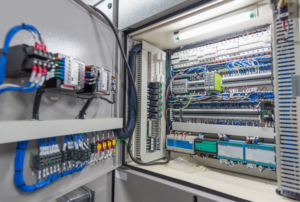
7. Ergonomics and clarity of the installation
The EN 60204-1 standard emphasizes that the electrical installation must be designed to provide easy access to components and minimize the risk of human error. This ergonomics is influenced by, among other things:
- Layout of components in the control cabinet: sufficient space for wiring, component ventilation, and logical grouping of devices.
- Equipment labeling: clear descriptions for pushbuttons, contactors, safety relays, or I/O modules.
- Cable routing: avoiding mixing power and signal cables in the same cable duct.
The last point is particularly important if the machine includes high-power cables (e.g., supplying motors, converters) as well as measurement leads from sensors. Strong signals from power or motor cables can introduce interference into control and measurement cables, causing incorrect readings and unplanned downtime. In line with design principles and machine safety:
- Power and signal cables should be routed in separate cable ducts or on different duct levels.
- For low-current signals, appropriate shielding is used, and the cable shield should be properly grounded.
- Minimum distances should be maintained between power cables and signal cables, especially at high frequencies (e.g., in systems with inverters).
Ignoring these rules can result in “unexplained” alarms, incorrect sensor operation, and ultimately lead to wrong control decisions (e.g., stopping the machine due to a false indication, or even situations that endanger operator safety).
8. Internal machine lighting
An often overlooked—but extremely important—area is internal machine lighting (e.g., the working chamber and operator access zones). The standard states that areas requiring adjustment or maintenance must provide an illuminance of at least 300 lx.
- Insufficient lighting means a higher risk of mistakes when changing tools, adjusting parameters, or assessing component wear.
- Example: in a chemical reactor (part of a process installation), poor lighting can lead to an incorrect assessment of the substance level and, as a result, a leak.
Properly designed lighting is not only about meeting standards—it is also another lever for safety and operational efficiency.
9. Protection against electromagnetic interference (EMC)
In an era of widespread automation and extensive communication networks (e.g., industrial automation communication protocols such as PROFIBUS, EtherCAT, or SAFETYNET), correct design and protection against electromagnetic interference are essential.
- EMC filters and shielded cables help minimise interference.
- Cable route segregation (separating power cables from signal cables) prevents interference from coupling between them.
In practice, in machines with defect detection systems, incorrect cable routing can cause erroneous sensor readings, leading to incorrect classification of finished products. It is also important to remember that the electromagnetic compatibility (EMC) directive requires every machine to meet specified limits for emissions and immunity to interference.
10. Testing and verification of the electrical installation
The final—yet equally important—step is thorough testing of the entire installation before placing the machine on the market or restarting it after modifications. This includes:
- Measuring insulation resistance and protective conductor continuity.
- Verifying the operation of protective devices (residual current devices, overcurrent protection, safety relays, etc.).
- Emergency simulations (e.g., pressing the emergency stop button and assessing the system response).
Skipping these tests can result in a situation where the first serious short circuit exposes hidden faults, ending in a dangerous incident. In addition, if you intend to obtain CE certification for machines or carry out the machine conformity assessment process, proper test reports form the documentation confirming that the requirements have been met.
Safe operation and regulatory compliance
Following the principles set out in EN 60204-1 is not only a formal requirement linked to the Machinery Directive or the new EU Machinery Regulation 2023/1230, but above all a guarantee of operator safety and machine reliability. A well-designed and well-documented electrical installation:
- Protects human health and life – by minimising hazards related to electric shock or power supply system failures.
- Ensures efficiency – thanks to proper cable organisation, correct selection of protective devices, and proper grounding, machines operate more stably and are easier to service.
- Reduces costs – fewer production stoppages and a lower risk of expensive repairs or claims.
It is worth supporting the implementation of the above guidelines with training and consultations with experts in machine design and construction, especially for more advanced technologies. A well-trained engineering team can anticipate the most common pitfalls already at the concept stage, which translates into shorter implementation time and faster achievement of business goals.
Remember—maintaining EN 60204-1 standards is an investment in safety, efficient production, and a positive brand image. If in doubt, consider carrying out a safety audit, consulting an authorised representative of the manufacturer (for imported machines), or performing an additional risk assessment. This way, you can be confident that your machine is not only legally compliant, but above all—safe in everyday operation.
EN 60204-1: 10 key principles
A defect state is a latent fault (e.g., damaged cable insulation) that may not produce any symptoms during machine operation. A failure means the machine stops or a clear malfunction occurs, often resulting from a previously unnoticed defect.
Because a defect may not be visible to the operator and still pose a risk of electric shock, a short circuit, or a fire. Regular inspections and proper safeguards help detect a fault before it turns into an accident or a serious breakdown.
EN 60204-1 refers to IEC 60445: PE is yellow-green, N is blue, and phase conductors (L) are typically black, brown, or grey. Clear identification reduces the risk of mistakes during servicing and retrofits.
It requires the use of, among other measures, basic and reinforced insulation and appropriately selected residual current devices (RCDs). In the example of abraded insulation, an RCD can quickly disconnect the power supply, limiting the risk of electric shock and damage.
Emergency stop buttons must be clearly visible and easily accessible, and the standard refers here to ISO 13850. Typically, this is a red button on a yellow background, positioned so that the operator can respond quickly.