
Key takeaways:
The article explains the role of technical drawing in the product life cycle and describes function-oriented and manufacturing-oriented approaches to dimensioning.
- A technical drawing conveys precise, unambiguous information about a design in engineering and manufacturing.
- Facilitates communication between design, production, quality control, and service and maintenance
- Contains data on the design, shape, dimensions, and tolerances of parts and assemblies.
- Functional dimensioning prioritizes dimensions critical to operation and selects tolerances to meet the required function
- Production dimensioning adapts dimensions and tolerances to the capabilities of manufacturing processes to reduce errors and costs.
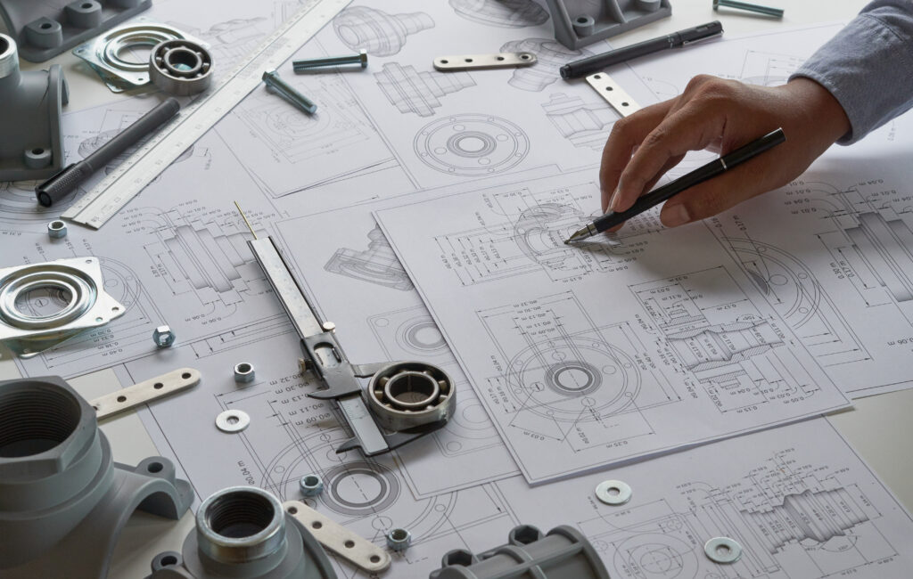
Technical drawing is a fundamental tool in engineering and manufacturing, used to present detailed design information in a precise and understandable way. It enables engineers, designers, and technicians to communicate concepts, specifications, and technical requirements in a standardised and unambiguous manner. Without technical drawings, the process of designing and manufacturing complex equipment and machinery would be far more difficult, and the risk of errors and misunderstandings would increase significantly. An introduction to technical drawing includes understanding its role at different stages of the product life cycle, from concept and design, through manufacturing, to quality control and servicing.
Why is technical drawing needed and what is it used for?
Technical drawing is an indispensable part of the machine design and construction and manufacturing process, playing a key role across many engineering disciplines. Its main purpose is to present detailed information about the design, shape, dimensions, and tolerances of technical parts and assemblies, making it one of the most important elements of a machine or production line’s operating instructions and technical documentation. Technical drawings are used by engineers, designers, technicians, as well as production and quality control personnel, to communicate technical information accurately.
Technical drawings are used in a wide range of applications:
- Design: They enable engineers and designers to create accurate models and plans that form the basis for further work, including structural verification supported by accurate models and plans.
- Manufacturing: They provide production personnel with the information needed to manufacture parts in line with requirements.
- Quality control: They help verify that completed parts conform to design requirements, thereby ensuring high product quality.
- Service and maintenance: They make it easier to identify spare parts and repair procedures.
Technical drawings make it possible to ensure that products meet functional, aesthetic, and safety requirements, which is essential for achieving high quality and reliability in manufactured products.
Technical drawing: function-oriented drafting (functional dimensioning)
Functional dimensioning, also known as function-oriented dimensioning, focuses on ensuring that parts and assemblies fulfil their intended functions. The key idea behind this method is to assign dimensions and tolerances in a way that guarantees the product will perform in accordance with the design assumptions.
Functional dimensioning includes:
- Defining functional requirements: At the outset, critical dimensions and tolerances that directly affect the function of the part are identified. An example is the diameter of a hole, which must be matched precisely to a shaft to ensure the correct fit.
- Prioritising dimensions: Critical dimensions that directly affect functionality are given priority and assigned tighter tolerances than less important dimensions.
- Analysing the effect of tolerances on function: An analysis is carried out to determine how dimensional changes within tolerance limits affect the operation of the entire system. This makes it possible to define tolerances optimally so that reliable performance is achieved at minimum manufacturing cost.
Benefits of functional dimensioning:
- Improved reliability: By focusing on critical dimensions, products are more reliable and perform their functions predictably.
- Cost reduction: Optimal tolerances minimise waste and the need for costly rework, reducing manufacturing costs.
- Easier communication: Precise definition of critical dimensions improves communication between designers and engineers, manufacturers, and quality control teams, leading to better collaboration and a clearer understanding of design requirements.
Functional dimensioning is therefore a key part of the design process, ensuring that the final product performs as intended, meets user expectations, and complies with quality standards.
Technical drawing: production-oriented drafting (manufacturing dimensioning)
Manufacturing dimensioning focuses on facilitating the production process by ensuring that dimensions and tolerances are aligned with the capabilities and limitations of manufacturing technologies. This dimensioning method is important for optimising manufacturing processes, reducing costs, and ensuring production consistency.
Manufacturing dimensioning includes:
- Accounting for manufacturing processes: Dimensions are selected to match manufacturing methods such as machining, plastic injection moulding, casting, or CNC techniques. This minimises the need for additional machining and adjustments.
- Reducing production errors: Proper dimensioning that takes manufacturing processes into account reduces the risk of errors, leading to higher efficiency and less waste.
- Cost optimisation: Precise dimensioning makes it possible to use standard tools and machines, which lowers production costs and improves output. For example, using dimensions aligned with industry standards can significantly reduce the cost of serial production.
Benefits of production dimensioning:
- Higher efficiency: Production becomes more efficient by eliminating unnecessary operations and adjustments.
- Lower costs: Optimising dimensions to suit machine capabilities and manufacturing processes helps reduce production costs, which is especially important in mass production.
- Quality assurance: Adapting dimensions to manufacturing processes helps maintain high product quality by eliminating potential sources of errors and deviations.
Production dimensioning is therefore a key part of the design process, enabling smooth and efficient production while ensuring high quality and consistency of the finished products.
Design for Assembly and Design for Manufacturing
Design for Assembly (DFA) and Design for Manufacturing (DFM) are key design methodologies aimed at streamlining assembly and production processes.
- Design for Assembly (DFA):
- Focuses on simplifying assembly by minimising the number of parts and reducing the complexity of the assembly process.
- Key principles include reducing the number of components, eliminating the need for adjustments, designing self-centring and self-locating parts, and improving access and handling during assembly.
- One example is introducing symmetry into designs to make assembly easier, as well as eliminating elements that could be installed incorrectly.
- Design for Manufacturing (DFM):
- Focuses on optimising designs for ease and cost-effectiveness of production.
- It promotes the use of standard components, materials, and manufacturing processes, helping reduce costs and improve quality.
- Examples include using standard parts and materials and minimising production operations by integrating multiple functions into a single component.
Using DFM and DFA methods leads to significant savings in production costs and improves product quality and reliability.
Technical drawing: Comparing functional and production-oriented drawing
Function-oriented drawing (functional dimensioning) and production-oriented drawing (manufacturing dimensioning) are two different methods that serve different purposes in the design and manufacturing process. Each method has its own advantages and is used depending on project requirements and manufacturing processes.
Main differences between the methods:
- Purpose and priorities:
- Functional dimensioning: Focuses on ensuring that parts perform their intended functions in line with the design assumptions. A key aspect here is the accuracy of interfaces between parts. For example, if there are two drawings—one showing holes and the other pins—both drawings will include the same spacing dimension to ensure a precise fit between these elements. Tolerances are critical here to ensure the interfaces function correctly.
- Production dimensioning: Focuses on ease of manufacture and cost minimisation. In this case, dimensions may be defined from datums, which is more advantageous from a manufacturing standpoint, but it can lead to greater variation at interfaces. For example, dimensions taken from datums may differ, which can result in variable tolerances and affect the accuracy of part fit.
Examples of how both methods are used in practice:
- Functional dimensioning:
- Used in designs where precision and reliability are critical, for example in the aerospace or medical industries. One example is the design of engine components, where critical interface dimensions, such as the spacing of mounting holes, must be specified very precisely to ensure proper operation of the entire system.
- Production dimensioning:
- Used in mass production, where cost and efficiency are the priority, for example in the electronics industry or toy manufacturing. One example is the housing of an electronic device, where dimensions are defined from production datums, allowing faster and lower-cost manufacturing, but potentially affecting the accuracy of assembly of individual parts.
Impact on dimensional tolerances:
- Functional dimensioning: Tolerances are tighter in areas that are critical to product performance. In this case, what matters is the tolerance of the interface itself rather than the dimension from the datum. This ensures the product will perform as required, but it can increase manufacturing costs due to stricter precision requirements.
- Manufacturing dimensioning: Tolerances are aligned with manufacturing capability and are more flexible in areas that do not directly affect functionality. This approach helps reduce costs and improve production efficiency, but it may involve trade-offs in the precision of certain features.
A comparison of these two methods shows that the right approach depends on the specific project requirements and the available manufacturing technologies. In practice, a combination of both methods is often used to balance precision and efficiency, enabling optimal use of resources and high product quality.
| Criterion | Functional Dimensioning | Manufacturing Dimensioning |
|---|---|---|
| Main objective | Ensure that parts perform their intended functions as designed | Optimise the manufacturing process and minimise costs |
| Priority | Critical interface dimensions between parts | Datum dimensions adapted to manufacturing processes |
| Tolerances | Tighter tolerances on critical dimensions | Flexible tolerances in areas less important to function |
| Application example | Precise positioning of holes and pins for proper fit | Dimensions defined from manufacturing datums, e.g. from part edges |
| Accuracy | High accuracy requiring precise measuring tools | Matched to the technological capabilities of the available machines |
| Quality control | Focused on critical dimensions and product functionality | Focused on compliance with manufacturing processes and waste reduction |
| Costs | Higher costs due to stricter precision requirements | Lower production costs through process optimisation |
Technical drawing: GD&T (Geometric Dimensioning and Tolerancing)
GD&T, or Geometric Dimensioning and Tolerancing, is an advanced dimensioning and tolerancing system that makes it possible to define the shape, orientation, location, and dimensional variation of mechanical parts with precision. GD&T is widely used in the automotive industry, aerospace, and the manufacture of medical devices, where precision requirements are especially high.
Key elements and principles of GD&T:
- Nominal dimensions: Define the ideal dimension values without taking tolerances into account.
- Geometric tolerances: Define the permissible variation in a part’s form, orientation, location, and runout. The main types of geometric tolerances are:
- Straightness: Ensures that lines are straight within the specified tolerance limits.
- Flatness: Ensures surface flatness within specified limits.
- Roundness: Ensures that each circular cross-section is uniform.
- Cylindricity: Specifies that the cylindrical form is uniform over its entire length.
- Parallelism, perpendicularity, and angularity: Define the relative orientation of surfaces or axes in relation to one another.
- Datums: These are geometric references used as the basis for defining other dimensions and tolerances. Datums are extremely important in GD&T because they provide a common reference framework for measurement and quality control.
- Form and position tolerance control: Precisely defines the permissible deviation from ideal positions and shapes, which is essential for ensuring part compatibility during assembly.
GD&T is not only a tool for defining dimensions and tolerances, but also a language of technical communication that enables designers and engineers and manufacturers to communicate design and production requirements accurately. By applying GD&T, it is possible to achieve high precision, quality, and product conformity, which is essential in modern industry.
Technical drawing: Dimension chains and tolerance analysis
Dimension chains and tolerance analysis are key concepts in engineering and technical design that help ensure the precision and functionality of complex mechanical assemblies. Proper management of these aspects is essential to ensure that components fit correctly and work together properly in the finished product.
Dimension chains
A dimension chain is a sequence of dimensions linked so that each dimension relates to the previous and next one in the sequence. Its purpose is to determine the final dimension as the sum or difference of the individual component dimensions.
Tolerance analysis
Tolerance analysis assesses how permissible dimensional deviations affect the functionality and quality of the finished product. In practice, this means analysing how dimensional variation within tolerance limits influences the performance of the entire system.
Practical applications
- Design and manufacturing: When designing mechanical assemblies such as gearboxes, engines, or valves, dimension chain analysis is essential to ensure that all components work together correctly. For example, in automotive engines, accurate dimensioning and tolerance analysis are critical to smooth operation and long service life.
- Quality control: Tolerance analysis also supports the development of quality control strategies that help identify and eliminate manufacturing errors. Proper tolerance management minimises the risk of defective products and reduces costs associated with rework and complaints.
Dimension chains and tolerance analysis are therefore key engineering tools that make it possible to design and manufacture complex systems with high precision while ensuring compliance with functional and quality requirements.
Technical drawing: Reference dimensions
Reference dimensions are a key element of technical drawings, enabling the precise and unambiguous definition of the position and size of design features. These dimensions are not directly tied to the manufacturing process; instead, they serve as references for other dimensions and help with drawing interpretation.
Examples of use:
- Mounting holes: Reference dimensions can indicate the exact location of mounting holes relative to datum features. For example, if a plate has several holes, reference dimensions can define the distances between them, making assembly and quality control easier.
- Quality control: Reference dimensions can be used to verify that the dimensions of the finished product comply with design requirements. This makes it possible to check quickly and accurately whether all features are positioned correctly.
- Benefits:
- Improved communication: Reference dimensions provide an additional layer of information that makes communication easier between designers and engineers and production personnel. They help define the position and size of design features clearly, reducing the risk of misinterpretation.
- Greater precision: Reference dimensions make it possible to define the position and size of features more accurately, which contributes to improved product quality and reliability.
Impact on precision and workmanship quality
Although reference dimensions are not used directly for manufacturing, they play a key role in ensuring precision and workmanship quality. They make it possible to define feature positions accurately, which is especially important in complex designs where small deviations can significantly affect product functionality and durability.
Differences between nominal and actual dimensions:
- Nominal dimensions: These represent theoretical dimensions without accounting for manufacturing errors. They are specified on drawings as target values to be achieved during production.
- Actual dimensions: These are the dimensions actually measured on manufactured parts. Actual dimensions always include some deviation from nominal dimensions, provided they remain within the specified tolerances.
Importance in the context of GD&T and ISO:
- GD&T:
- Precision: In the GD&T system, nominal dimensions are the reference point for defining geometric tolerances. For example, if the nominal hole diameter is 10 mm, the tolerances may specify permissible deviations of +/- 0.1 mm, meaning the actual hole diameter may range from 9.9 mm to 10.1 mm.
- Consistency: GD&T ensures that all features meet functional requirements by precisely defining allowable deviations from nominal dimensions. This, in turn, enables accurate part fit and proper operation in complex assemblies.
- ISO:
- Standardisation: In ISO standards, nominal dimensions form the basis for defining international dimensional standards. For example, ISO 2768 specifies general dimensional tolerances for length, angle, radius, and other geometric dimensions that must be met in manufacturing.
- Compliance: By defining nominal dimensions and their tolerances in accordance with ISO standards, products manufactured in different parts of the world can be interchanged and assembled without fit-related issues.
Nominal dimensions are therefore an essential part of technical drawings, providing the basis for defining tolerances and quality standards in both GD&T systems and ISO standards. They make it possible to achieve the high precision, quality, and product conformity that are critical across many industrial sectors.
Technical drawing plays a key role in the design and manufacturing process, enabling technical information to be communicated accurately and efficiently. This article discusses various aspects of technical drawing, including functional dimensioning, production dimensioning, the use of GD&T, ISO standards, dimension chains, and reference and nominal dimensions.
Functional dimensioning focuses on precisely defining interfaces between parts, ensuring product reliability and functionality. Production dimensioning, in turn, optimises manufacturing processes, reducing costs and increasing efficiency.
GD&T provides advanced tools for precisely defining geometric tolerances, which is crucial to ensuring conformity and quality in manufacturing. ISO standards introduce international standards that ensure product consistency and interoperability worldwide.
Dimension chains and tolerance analysis enable accurate management of dimensions and tolerances, which is essential for complex mechanical assemblies. Reference and nominal dimensions provide additional information needed to interpret technical drawings and ensure dimensional accuracy and conformity.
All of these elements work together to support the creation of precise, reliable, high-quality products used in sectors such as heavy industry, the pharmaceutical industry, and FMCG manufacturing.
Technical drawing
It is used to present clearly and precisely the design, shape, dimensions, and tolerances of parts and assemblies. It facilitates communication of technical requirements between design, manufacturing, and quality control.
They are used from concept and design through production to quality control, service, and maintenance. They help keep information consistent at every stage.
It provides production staff with the data needed to manufacture the part in accordance with the requirements. It also makes it possible to verify that the finished part complies with the design assumptions.
It involves assigning dimensions and tolerances so that components perform their intended functions. It prioritizes critical dimensions and analyzes the effect of tolerances on system performance.
It focuses on matching dimensions and tolerances to the capabilities and limitations of the manufacturing process. It helps minimize errors, optimize costs, and improve production consistency.