Table of Contents
Emergency Stop in Accordance with EN ISO 13850: Function, Requirements, and Design
The emergency stop system, also known as the emergency stop device, is a crucial component of a machine’s control system, designed for the immediate cessation of operations in hazardous situations. According to the EN ISO 13850 standard, it is a function intended to reverse or mitigate the effects of existing hazards to people and equipment, initiated by a single human action. In essence, the emergency stop allows operators to quickly halt machinery in the event of an accident or threat, preventing escalation and providing time for further action.
Machines should be equipped with at least one emergency stop device if determined necessary by a risk assessment. This requirement is outlined in both regulations and standards. Exceptions include machines where an additional emergency stop would not reduce risk or in handheld or manually guided machines. Generally, the presence of an emergency stop button is a standard requirement for machines posing operational hazards. However, the emergency stop does not replace other safety measures; it is a supplementary protective measure when other controls fail or an emergency arises despite existing safeguards.
Emergency stops are typically used when an operator or other individual perceives a danger requiring immediate machine cessation. Examples include clothing entanglement, material collision, a person falling into a robot’s working area, or mechanical failure causing unusual noise or vibration. Pressing the emergency stop should immediately halt dangerous machine movements, minimizing incident impacts, such as injuries or equipment damage. Importantly, emergency stops are intentional operator actions—a “manual safety brake” that operates on human command, not automatically. Thus, it serves as the last line of defense in the safety hierarchy, activated only when other preventive measures fail.
Emergency Stop and Safety: Requirements of EN ISO 13850
Despite its clear safety connection, the emergency stop function is not classified as a typical ” safety function” under machine safety standards. The PN-EN ISO 13850 standard explicitly states that the emergency stop function is a supplementary protective measure. It cannot substitute other protective measures like guards, locks, or sensors, nor other safety-related control functions. Machines should not be designed to replace proper hazard shielding or elimination with an emergency stop. For example, if a conveyor poses a limb entrapment risk, merely installing a cable emergency stop along the conveyor is insufficient—physical guards or other risk reduction measures are necessary, with the emergency stop as an additional safeguard for extraordinary situations.
Moreover, the emergency stop device does not prevent unexpected machine startup. A common misconception is using a pressed emergency stop button as a lock to prevent machine reactivation during maintenance. The PN-EN ISO 13850 standard clarifies that the emergency stop function cannot be considered a means to prevent unexpected startup. In other words, a pressed emergency stop is not equivalent to disconnected power. Machines should not be left in an emergency stop state during interventions, assuming it ensures non-reactivation—other procedures like energy isolation and lockout (LOTO) per PN-EN ISO 14118 (formerly PN-EN 1037) are intended for this purpose. The key in an emergency stop (in key-operated mushroom buttons) does not replace proper main power disconnection. The emergency stop is not designed as a permanent lock—it is a stopping mechanism, not a safeguard against automatic startup.
In summary, from an engineering risk assessment perspective, the emergency stop does not reduce inherent risk. It is an “emergency brake”—activated when a hazard is present or has occurred, not eliminating it at the source. This is confirmed by the PN-EN ISO 12100 standard, stating that the emergency stop function is a supplementary protective measure (not lowering the risk category itself). Nevertheless, the emergency stop system must be designed according to safety principles to function reliably when needed. While not a formal safety function, its implementation should meet stringent safety requirements (e.g., system reliability). Subsequent sections discuss these requirements.
Placement of Emergency Stops and Division into Control Zones
When designing an emergency stop system for a machine or production line, consider the placement of emergency stops to ensure accessibility from any location where a quick stop might be necessary. The EN ISO 13850 standard emphasizes that emergency stops should be installed at each fixed operator station (control panel) and in other locations identified by the risk assessment.
In practice, this means placing “mushrooms” within reach of machine operators and along areas where materials or people move (e.g., along conveyors, near service access zones). It is crucial that anyone who can perceive a hazard can immediately reach an emergency stop without risking their own safety (e.g., the stop should not be placed where reaching it requires entering a danger zone).
Mounting height for emergency stops should follow ergonomic recommendations. For mushroom and other hand-operated stops, installation at a height of 0.6 m to 1.7 m above the floor (or platform where the operator stands) is recommended.
This range ensures that both shorter and taller individuals can comfortably hit the button with their hand or arm. For foot-operated devices (emergency pedals), installation directly on the floor level, in a fixed position where the operator stands, is recommended—so they can easily press the pedal with their foot if needed. Generally, emergency stops should be distributed throughout the machine space so that regardless of where a hazard occurs, a button is always within a few meters.
Control Zones of Emergency Stops
The 2015 revision of the EN ISO 13850 standard introduced the concept of dividing a machine into emergency stop zones (known as span of control). This means that for very large or complex installations, it is not always necessary to stop the entire machine when a single emergency stop is pressed—you can limit the stop effect to a specific machine zone if the risk analysis allows it. The intent of this provision is to avoid situations where stopping the entire system in response to a local hazard could cause unnecessary consequences (e.g., secondary hazards or significant production losses). Imagine a long production line composed of many sections and stations, where dozens of operators work. When one worker notices a dangerous incident in their area, it is not always necessary or desirable to stop the entire line—often, stopping only the part where the hazard occurred suffices. This way, the rest of the line can continue to operate (if safe), and the risk does not transfer to other areas.
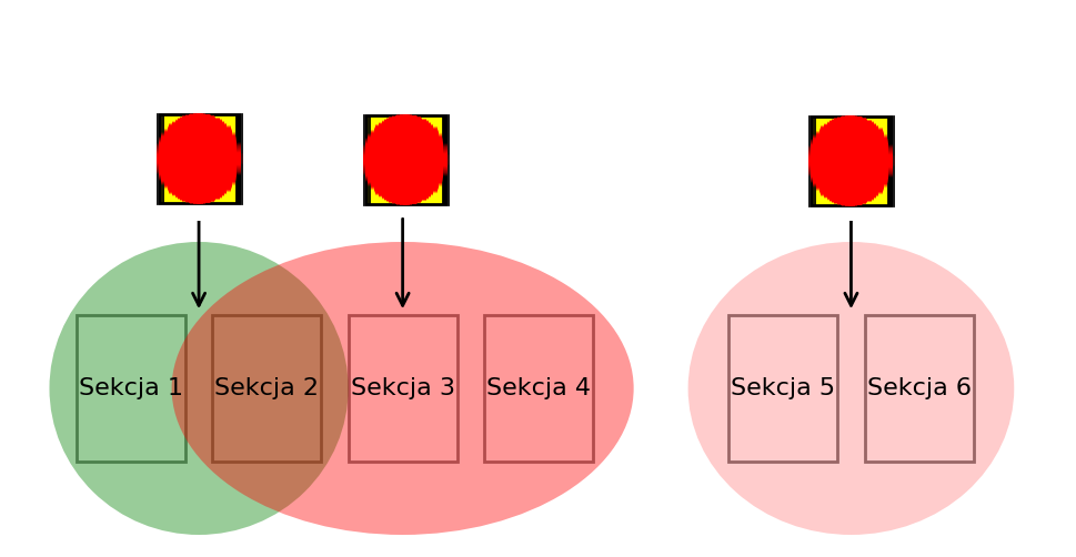
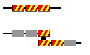
In practice, this is achieved by assigning specific emergency stops to defined machine zones. Each emergency stop button halts only the sections within its zone. Zones can overlap or be adjacent—what matters is that they collectively cover the entire machine (unless certain parts do not require an E-Stop). These zones must be clearly defined and marked, so users know which parts of the machine will stop when a specific emergency button is pressed. Information in the manual is insufficient—the standard requires clear zone identification directly on the machine. It is recommended to use emergency stop zone pictograms next to control devices. The current standard provides examples of such pictograms: they may depict a machine diagram with the covered area shaded. Examples include situations where the zone covers the entire machine or only selected sections. The pictogram’s color scheme is not strictly defined—black and white symbols are common, though using yellow-black warning colors seems natural. The key is that the marking is durable and understandable for the crew.

The graphic shows machine sections (1–6) grouped into zones corresponding to different emergency stops. The green zone (left) covers sections 1 and 2; the red (middle) covers sections 2, 3, and 4; the pink (right) covers sections 5 and 6. Section 2 is within two zones, so pressing either of the two adjacent “mushrooms” will stop section 2. Such intentional zone overlap may result from risk analysis—e.g., two operators near section 2 each have their emergency stop, and activating either will halt that section.
Introducing zone division does not exempt from general emergency stop function requirements. When opting for such division, manufacturers must ensure that operators do not have to wonder if a particular emergency stop will halt the correct machine part. In an emergency, a person should immediately press the nearest “STOP”—the system must be designed so that regardless of zone configuration, this action always improves the situation, not worsens it. For example, if stopping only part of the line could generate additional hazards (e.g., product collisions, material spills, synchronization loss causing danger), then the line should not be divided into zones. Zone boundaries must result from thorough risk analysis and testing. Typically, simpler machines use a single zone covering the entire machine (all E-Stops stop everything), while large complex installations use logically defined zones (e.g., material supply section, processing section, receiving section—each with its emergency circuit). In all cases, the rule is that each emergency stop zone must be clearly assigned to emergency stop devices and vice versa—each emergency stop must have a defined scope of action, known to users.

Types of Emergency Stop Devices
Devices implementing the emergency stop function come in various designs, tailored to different machine types and situations. The PN-EN ISO 13850 standard covers all these devices with general requirements, but execution details may vary. Here are the main types of emergency stops found in practice:
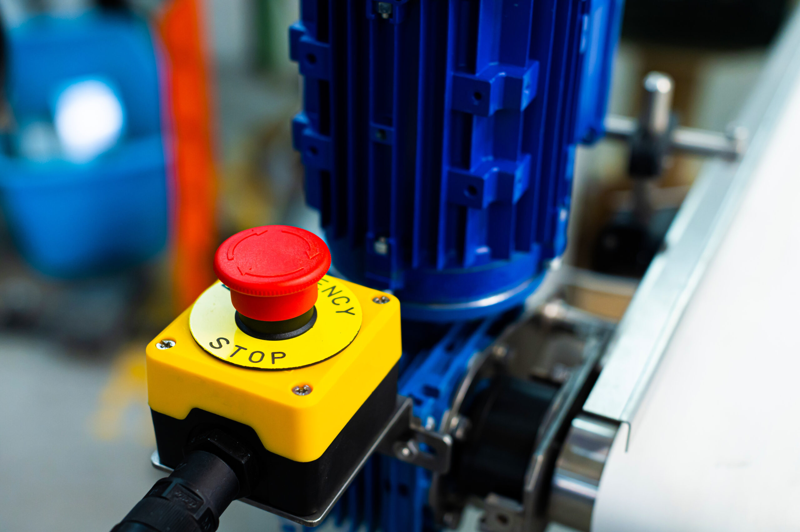
- Mushroom button – The most common type of emergency stop. It is a large, red mushroom-shaped button, often with a yellow base, designed to be hit with an open hand. It is mounted on control panels, machine enclosures, line walls, etc. Once pressed, it remains locked (latching mechanism); unlocking occurs by twisting or pulling up the mushroom. Mushroom buttons are designed to withstand significant impact forces and be easily detectable by touch. Inside, they contain NC (normally closed) contacts that open when pressed, generating a stop signal in the safety circuit. Due to their simplicity and reliability, these buttons are standard on most machines.
- Rope (cable) switch – This is an emergency device designed to protect long machine sections or conveyor belts. It consists of a triggering mechanism connected to a long steel cable (rope) stretched along the machine. Pulling the cable anywhere activates the emergency stop (the mechanism tensions the cable and triggers stop contacts). Typically, emergency cables can be several tens of meters long, allowing protection of, for example, an entire conveyor. Rope switches often also have an integrated mushroom button on the end mechanism (providing an additional pressing option). These devices usually have a tension indicator and require correct tensioning—a too loose or broken cable also triggers an emergency stop (a form of damage self-check). They are used along production lines, packaging lines, technological chains—anywhere the operator may not have time to reach the nearest button but can reach the cable surrounding the area.
- Emergency foot pedal – A special foot switch serving as an emergency stop. It resembles a pedal (foot button) often with a guard to prevent accidental pressing. Used where the operator’s hands are occupied or typically controls the machine with their foot (e.g., in some presses, textile machines, foot-operated devices). Such a pedal, when strongly pressed, snaps into the emergency position (latching mechanism like a mushroom). Lifting the guard and mechanical reset are required to restore it. In practice, emergency pedals are less common than mushroom buttons but are found, for example, on machines where the operator’s hands must hold material, allowing them to stop work with their foot. It is important that the emergency pedal is firmly attached to the floor and easily detectable by foot.
- Pull/rod emergency switch – Some machines use emergency rods or handles that can be pulled or pressed to stop. Examples include pressure bars (bump bars) on machine fronts—a long bar that, when hit by a body or hand, triggers an emergency stop. Another example is a emergency switch in handle form to pull (often found on rotary machines, where pulling a lever causes a stop). These solutions perform an analogous function, though electrically they often still work with a button/cable mechanism. It is crucial that they also have a latch—e.g., a safety bar with an additional contact that must be manually unlocked after activation to reset the emergency state.
- Remote emergency stop on a portable panel – It is worth mentioning that on portable control panels, such as operator pendants or radio control panels, red emergency buttons are also installed. They serve the same role as fixed stops on the machine. Structurally, they are usually standard mushrooms, just mounted on a remote case. The specificity is the need to maintain communication—for example, a radio panel must have reliable (often dual-channel) communication with the machine to ensure the E-Stop signal always reaches it. As mentioned, such mobile E-Stops do not exempt from having fixed ones—they are merely a convenient addition for remotely operating personnel.
Regardless of physical form, all the above devices must fulfill the same emergency stop function according to the standard. They should be appropriately marked with red (and yellow background), have reliable safety contacts, and a mechanism requiring manual unlocking. The choice of stop type depends on the machine’s nature: for example, mushroom buttons work well at stations, cables along long sections, pedals for foot operation, etc. Often different types are combined—e.g., a machine may have mushrooms on panels and a cable along the material feed zone. All these elements are connected in one emergency stop circuit (or several circuits corresponding to zones)—pressing any triggers an emergency stop according to the stop category.
The emergency stop is a key element of the machine safety system, though it does not reduce risk preventively. It serves as the last safeguard—allowing a person to stop dangerous movement in a critical moment and prevent accident escalation. According to PN-EN ISO 13850, this function should be treated as a supplement to other protective measures, not their substitute. A properly designed emergency stop system works whenever needed, is intuitive to use (large red mushroom, cable, etc.), does not create new hazards (appropriate stop category, thoughtful zone division), and is reliable (meeting required PL, regular tests). Engineers designing machine control systems must adhere to standard guidelines—from “mushroom” placement and marking to their integration with the control system. This way, the emergency stop will effectively fulfill its role as the “yellow safety button” that can save an operator’s health or life in an emergency. However, remember that the best approach is to avoid situations requiring E-Stop use—through proper safeguards, training, and work organization. The emergency stop remains the last, but reliable line of defense.
FAQ:
The emergency stop button should be red on a yellow background, without additional descriptions or symbols.
They should be easily accessible to operators, considering machine size, workstation layout, and hazard zones.
Yes, a machine can be divided into multiple control zones if stopping the entire machine could cause additional hazards or unnecessarily affect production.
Category 0: Immediate power disconnection to drive elements, causing uncontrolled machine stop.
Category 1: Controlled machine stop using control systems, followed by power disconnection.
Category 2: Controlled machine stop with power maintained to drive elements.
In addition to PN-EN ISO 13850, consider:
PN-EN ISO 12100: General principles for designing safe machines.
PN-EN 60204-1: Requirements for machine control systems.
Zobacz także:
Napisz do nas!
Chętnie odpowiemy na Twoje pytania!
