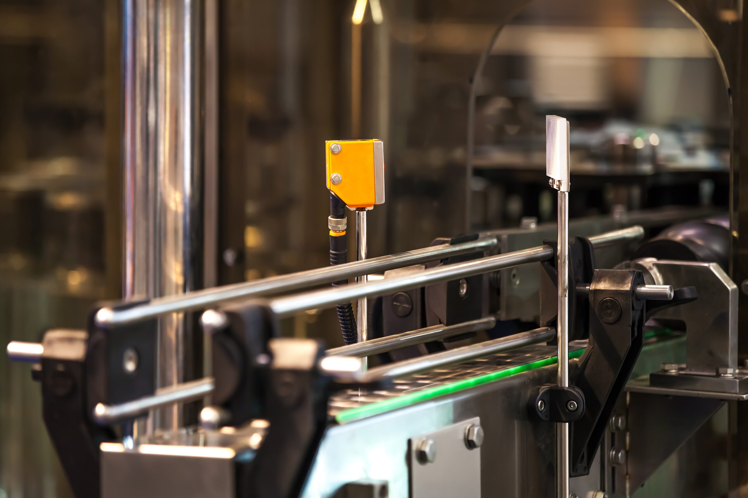
Did you know that any sensor—from inductive to pressure to RFID locks—can serve a safety function if equipped with the right redundancy and diagnostics? While the term “safety sensors” is commonly used, there is no universal category for these sensors. The key lies in how a sensor is integrated into the control system and whether it meets the standards of PN-EN ISO 13849-1 (Performance Level) and PN-EN 62061 (SIL). This article delves into how various types of sensors (e.g., inductive, pressure, limit switches, RFID, safety switches) can support or fulfill machine safety functions.
Table of Contents
Sensors and Machine Safety
According to the machinery directive and the new EU regulation on machinery, manufacturers or industrial automation integrators must ensure that machines are safe for users. Part of this process involves conducting a risk assessment and designing appropriate safety systems.
Many people equate safety with safety switches (e.g., guard locks), but in practice, any sensor, when used in a safety circuit, can support a safety function. The condition is meeting the requirements to achieve the appropriate Performance Level (PL) or Safety Integrity Level (SIL).
Safety Sensors: Evaluation Criteria for PL and SIL
PN-EN ISO 13849-1 (Performance Level)
- Defines safety levels from PL a to PL e.
- The higher the level (e.g., PL e), the lower the allowable probability of a safety function failure.
- Achieving PL e requires redundancy, diagnostic coverage (DC), and confirmed reliability levels of individual components (MTTFd).
PN-EN 62061 (SIL) / EN 61508
- Indicates safety integrity levels from SIL 1 to SIL 4.
- For industrial machines, typical requirements are SIL 2 or SIL 3.
- Designing a safety function for SIL 3 requires more than just a sensor with a signal output—it needs an advanced control architecture (safety controller, safety relay, or safety I/O module).
Important: In both approaches, a critical aspect is whether the system can detect and respond to a sensor failure, such as ensuring signal path redundancy.
Examples of Sensors as Safety Elements
Sensors are typically categorized by measurement principle (inductive, optical, pressure, etc.), but from a safety perspective, how the designer integrates them into the control system and their reliability parameters are more important.
Inductive Sensor
- Application: Detects the presence of a metal element (e.g., actuator position, mechanical lock).
- Function in safety system: If monitoring the position of a critical machine part (e.g., stopped punch) is necessary, two inductive sensors in a dual-channel setup can detect a failure in one of them.
- Safety versions: Some manufacturers offer inductive sensors with additional diagnostic wires, facilitating PL d/e or SIL 2/3 achievement.
Pressure Sensor
- Application: Monitors pressure in hydraulic or pneumatic systems.
- Function in safety system: Can shut down the machine or initiate a safe state when pressure exceeds allowable levels.
- Limitations: To qualify as a safety circuit element, a pressure sensor must have declared reliability indicators and enable (at least at the system level) monitoring of potential failures or deviations from the norm.
Safety Switches on Guards
- Safety classic: Limit switches with forced opening, safety locks with interlocking, cable switches on conveyor belts.
- Redundancy: Manufacturers increasingly offer dual-channel outputs (4-6 wires) and internal diagnostics.
- RFID coding: Modern locks and non-contact limit switches often feature RFID identification, making manipulation (replacing an element with another) more difficult.
Light Curtains and Barriers
- Application: Secures access zones, e.g., around presses or industrial robots.
- Safety level: Most barriers on the market declare achieving PL e / SIL 3, provided proper installation and configuration.
- Additional functions: Some have advanced self-diagnostics, blanking or muting differentiation (process adaptation), enhancing functionality without reducing safety levels.
RFID-Coded Sensors
- Main advantage: Difficult to manipulate, as each RFID actor is “paired” with a specific reader.
- Serial connection capability: Many allow for daisy chaining, connecting multiple sensors sequentially while maintaining high diagnostic levels.
- Application: Mainly on guards and doors, but also in more complex projects (e.g., monitoring the position of interchangeable modules in machines).
Safety Sensors: Achieving High Safety Levels (PL e / SIL 3)
- Redundancy (dual-channel)
- Two independent signal paths allow for detecting a sensor failure.
- Example: Instead of one inductive sensor, two parallel monitoring the same event; a safety sensor with two OSSD channels in one housing.
- Advanced diagnostics (DC – Diagnostic Coverage)
- The sensor should signal short circuits, open circuits, or signal blockages.
- In practice: OSSD outputs, transmission protocols (e.g., IO-Link Safety), test lines.
- Reliability parameters
- The manufacturer must provide data such as MTTFd, PFH, or SIL indicators for computational tools (e.g., SISTEMA).
- The better documented the device, the easier it is to prove achieving PL e / SIL 3 in machine risk assessment.
- Appropriate control system architecture
- Even the most advanced sensor won’t guarantee safety if it doesn’t work with a safety controller or relay tailored to the standard’s requirements.
- Ensure compliant actuators (e.g., contactors with forced opening).
RFID Coding and Serial Connection – Modern Trends
RFID Coding
- Coding level: In PN-EN ISO 14119, low, medium, and high security levels are distinguished. RFID often ranks higher as the sensor recognizes the transmitter’s unique code.
- Benefits: Makes system bypassing (tampering) more difficult, higher compliance with categories 3 or 4 (PL d/e).
Serial Connection (Daisy Chain)
- Why popular? Reduces the number of wires and safety controller inputs. Instead of 10 cables for 10 sensors, one chain is used.
- Does it lower safety? In modern solutions, no—each sensor in the series can signal its status, maintaining high diagnostics (e.g., PL e / SIL 3).
Safety Sensors: Implementation and Practical Tips
- Conduct a risk assessment
- Check if the machine requires PL e / SIL 3 or if a lower level (e.g., PL d / SIL 2) suffices.
- Excessive requirements can increase costs, but underestimation risks insufficient protection.
- Select appropriate sensors
- Ensure the manufacturer provides parameters for calculations (MTTFd, DC, PFH).
- Consider RFID sensors or reinforced constructions dedicated to safety—they usually have ready certifications from notified bodies.
- Design redundancy and diagnostics
- High safety levels require dual-channel solutions (category 3, 4 per ISO 13849-1).
- Set diagnostic functions in the safety controller (or relay) to detect failures immediately.
- Use engineering tools
- SISTEMA software (or similar) allows verification of whether the assumed PL levels are achieved.
- For SIL (EN 62061), estimating the PFH parameter for the entire safety function is necessary.
- Ensure training and audits
- Machine safety training helps understand practical examples, avoid mistakes, and implement effective solutions.
- Regular safety audits keep the machine compliant with regulations (also considering future changes to harmonized standards and directives).
Contrary to common belief, there is no single universal “safety sensor”—there are any sensors that can serve a safety function if given the right conditions: redundancy, diagnostics, and a well-designed control architecture. The stakes are high, as it’s about operator safety and machine compliance with current regulations and standards.
- Inductive, pressure, or limit switches can become critical safety elements when you ensure dual-channel and damage monitoring.
- RFID and modern technologies effectively counteract tampering and false signals.
- Serial connection (daisy chain) while maintaining appropriate diagnostic levels simplifies installation and maintains PL e / SIL 3.
Ultimately, selecting and implementing the right sensors is not just a formal requirement (e.g., obtaining a declaration of conformity or meeting machinery directive requirements), but also a real investment in the safety and efficiency of the machine park. Want to ensure your project is failure-resistant? Consider consulting with an experienced industrial automation integrator, use a safety audit, and remember to continuously improve your knowledge—it truly pays off.
FAQ: Safety Sensors
The most commonly used are: mechanical sensors (latches, limit switches), non-contact (magnetic, RFID), light barriers, safety scanners, pressure-sensitive mats.
Selection depends on the type of hazard and work environment.
Mechanical sensors require physical contact (greater wear), while non-contact sensors operate without touch, offering greater durability and resistance to harsh conditions (moisture, dust, aggressive substances).
The choice is based on the machine’s risk assessment. Key factors include the type of hazard, required safety levels (PL/SIL), work environment, and machine operation specifics.
Yes, according to the Machinery Directive and national regulations, machines must have appropriate protective measures, which means using safety sensors. This is also necessary for CE marking.
The most common mistakes are: selecting the wrong type of sensor, incorrect placement, lack of redundancy, inappropriate safety system configuration, neglecting regular operational checks.
